On August 24, 2018, the first systematic PCBA rework seminar was held in Yutai Technology. At the meeting, Haotai Technology proposed an effective solution to the 13 major problems in the PCBA rework industry, and visited the PCBA rework equipment with the guests.
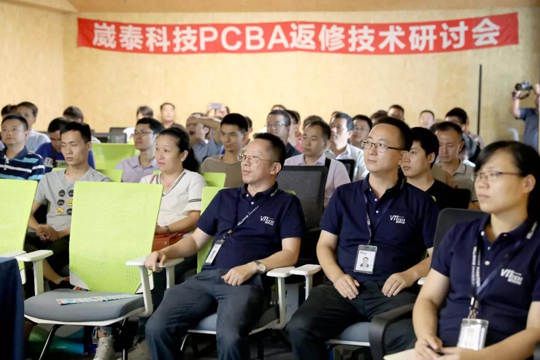
Figure 1
Haotai Technology Co., Ltd. is a supplier dedicated to providing customers with PCBA substrate rework process and equipment. Since its establishment in 2009, it has become a leader in the field of PCBA substrate rework.
It has established bilateral relations of cooperation and win-win with leading companies such as Huawei, Samsung, Foxconn, Jinbao Electronics, Hisilicon Semiconductor, Compal Computer and Delta.
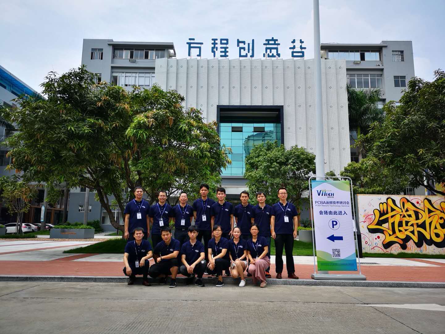
Figure II
The seminar started with a welcome speech by Mr. Du Honghua, President of Haotai Technology. President Du shared the company's business philosophy of value innovation, global vision and the company vision of a PCBA substrate return and process and equipment solution provider. Finally, I would like to extend a warm welcome to the guests!

Figure 3 Mr. Du Honghua, President of VTTECH, gave a welcome speech
With the rapid development of big data cloud business and smart electronic products, the volume of electronic products has become larger and smaller, and the requirements for performance and reliability of products have become higher and higher, which has brought about production and reverse repair processes. A bigger challenge.
Combining the above problems, Zhang Bo, the head of the Global Technical Support Department of the Biotech Engineering Center, took the 13 major problems in the PCBA rework industry as an example to analyze and explain the video of the perfect solution, which has aroused widespread concern in the industry.
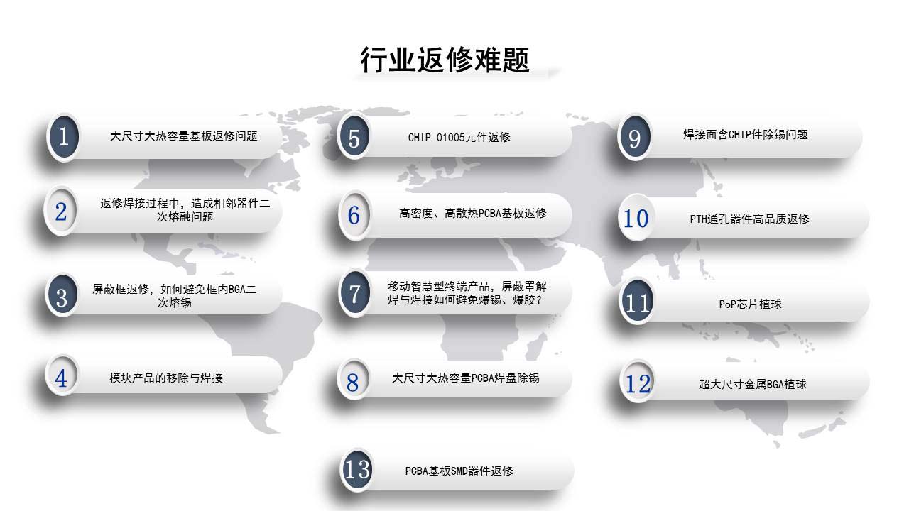
Figure 4 PCBA rework 13 big problems
1、 large size large heat capacity substrate repair problem
(1)The large substrate absorbs a large amount of heat, is unevenly heated, and the substrate is deformed.
(2)Large size BGA is unevenly heated, welding temperature difference is large, easy to solder or short circuit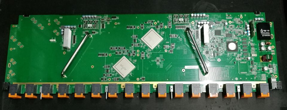
Figure 5 PCB size: length 840 * width 300 * thickness 4mm
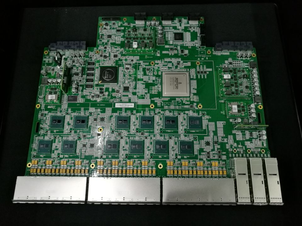
Figure 6 PCB size: length 500* width 450* thickness 4mm BGA size: 70*70mm
Case Studies
A customer produces high-end server motherboards, PCBA length * width 550 * 450 550 * 450 mm, thickness 4mm, BGA70 * 70mm. Customers use the US V * brand BGA rework station, the temperature difference between the BGA center and the edge solder ball is above 15 °C, and the BGA center is 100% connected to the tin when soldering;
The customer uses the VT-360L BGA rework station to test the temperature. The temperature difference between the BGA center and the edge solder ball is within 5 °C. CPK ≥1.6

Figure 7
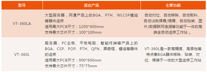
Large board large device rework application equipment
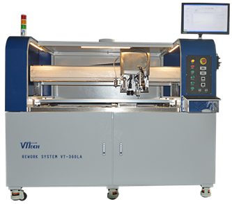
Figure 8 【automatic rework stationVT-360LA】
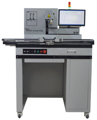
Figure IX 【Semi-automatic rework stationVT-360L】
Application customer
Foxconn, Beiying, Taiwan Zhibang, Xiangyang Tianyu…
2、Re-repair welding process, causing secondary melting problems of adjacent devices
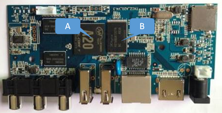
Figure ten
Case Studies
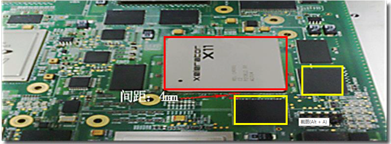
Figure XI
The above picture shows a customer's server product. The customer uses a BGA with lead-free solder balls. SMT is a lead process. There are two BGAs with a spacing of 4mm above 35*35mm and a BGA with a 4mm pitch. The customer uses a BGA rework station in the United States to repair the original BGA. Therefore, the customer requires a maximum soldering temperature of 225-230 ° C, and the temperature of adjacent BGA solder balls cannot exceed 200 ° C.
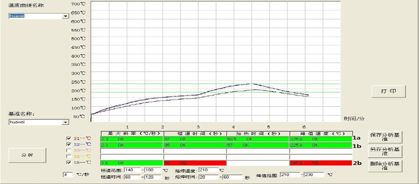
Figure twelve
The above picture shows that the repair on the VT-360 can pull the temperature difference of the adjacent BGA above 60 °C, away from the process critical point. The unique heating system of the VT-360BGA rework station is set up in different combinations to meet the requirements of the customer's process.
3、 Mask frame repair, how to avoid BGA secondary melting in the frame
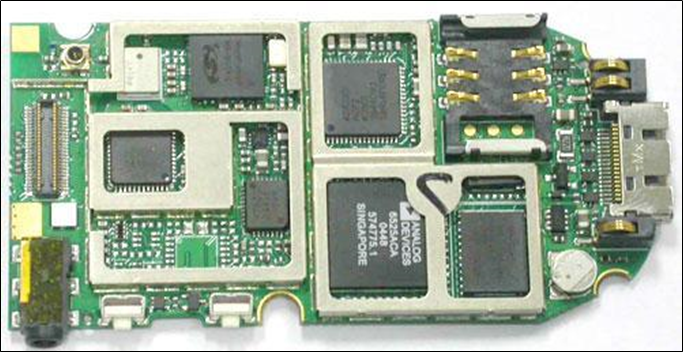
Figure 13
Currently, communication consumer electronics such as mobile phones and routers often use shields to prevent external electromagnetic fields and signal interference. In the production, defects are sometimes required to be repaired and removed by the shield. In this process, heat is diffused. The secondary reflow of the unrelated patch device in the shield, Often bring serious quality hazards

Figure 14
The above picture shows the high-frequency board produced by a customer. When the shield is removed and welded, the BGA in the shield can be tinned twice, which has potential quality hazards. The customer requested that the temperature of the BGA solder ball should not exceed 200 ° C when removing and soldering the shield.

Figure fifteen
The above figure optimizes the temperature parameters through the VT-360 BGA rework station, measuring the soldering point of the shield and the BGA solder ball point temperature in the shield. The profile is analyzed with the analysis software, and the actual results obtained are in accordance with the welding and protection temperatures of the various components.
4、 Module product removal and soldering

Figure sixteen
Modules are commonly found in cell phone communications and in-vehicle electronics, also known as letter boards. Rework difficulties:
1、No suction point when removing
2、It is easy to damage the components in the upper module after soldering

Figure XVII
The above picture is a module product produced by a customer. There are multiple BGAs on the PCB inside the shield cover of the module. The distance between the module and the connector PIN pin is 0.1mm. It can be removed by conventional methods, and it is easy to touch the shield. Cover or damage to the components inside the shield frame.
Apply our VT-360 rework station module rework solution to automatically remove and remove the entire module without damaging the shield cover and internal components.
5、 Chip01005 component repair

Figure 18
The Chip01005 device is a metric 0.4*0.2mm component that is widely used in smart terminal products. The difficulty in repairing is that the device is small in size and closely distributed, and the traditional manual cannot perform the rework operation. Therefore, how to rework the high quality has become the focus of many customers.

Figure 19
The 01005 rework solution of our VT-360 rework station can perfectly meet this challenge with a yield of over 95%.
Process: Use the VT-360 machine to remove the tin from the bad CHIP01005 device and its PAD, add a certain amount of solder to the PAD, and then mount the 01005 device to the soldered PAD and solder. The figure above shows a demonstration of the device removal tin and placement solder 01005 device.
6、 High-density, high-heating PCBA substrate repair

Figure twenty
The picture above is the current popular mining machine product. The front and bottom of the QFN chip are covered with a heat sink fin height of 25mm.
The traditional rework process is: disassemble the upper heat sink --- remove the bottom heat sink --- remove the QFN chip --- pad removal tin --- chip tin removal --- chip tin --- mount solder chip -- -welding bottom heat sink---heating and welding upper heat sink
Disadvantages of the traditional process: long repair time, cumbersome process, and many times of substrate heating (6 times) affect reliability
VTTECH solution: PCBA substrate tin removal machine removes upper heat sink and chip at the same time + pad removes tin---upper chip removes tin + tin--- BGA rework station mount soldering
Program features: simple repair process, high efficiency, less substrate heating
01005, shield cover, module rework application equipment
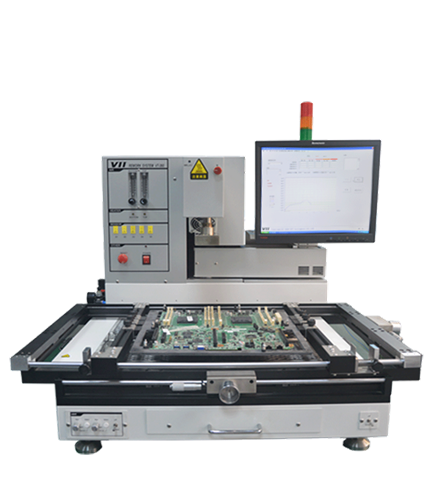
【Semi-automatic rework station VT-360M】

Application customer
Application customer...
7、 Mobile smart terminal products, how to avoid the explosion of tin and explosion when the shield is unsoldered and welded?
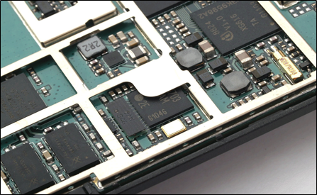
The shielding cover of the mobile communication terminal product mainly protects against electromagnetic interference (EMI), shields the RF original on the PCB board and the LCM. The material of the shielding cover is generally made of 0.2mm thick stainless steel and white copper. When a defect occurs in production, the shield frame is usually desoldered and removed. The following problems will be encountered during the repair process:
1、Thin substrate, deformation after heating stress, resulting in malfunction of other locations
2、During the heating process, the BGA in the frame is prone to bursting and exploding
3、Tightly spaced, manual can not remove tin
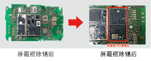
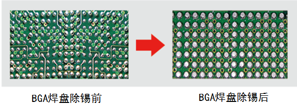
As shown in the figure, a customer's mobile phone product, the customer uses a traditional air gun to desolder the shield frame, resulting in BGA explosion in the frame.
VTTECH VT-610 series automatic PCBA tin removal machine removes the shield frame and removes tin, does not hurt PAD, does not explode tin, does not explode
8、 Large size large heat capacity PCBA pad in addition to tin
9、 Soldering surface containing CHIP parts to remove tin

The traditional tin removal method is soldering iron + tin tin with contact tin, this tin removal method has many potential risks, such as:
1、Soldering iron will melt copper after a long contact time
2、PAD loose or drop
3、Scratching the green oil around the PAD leads to poor soldering
If you use this method, the risk of tin removal on a 3mm thick substrate pad will increase greatly. The above product has many devices in the middle of the pad. It is easy to damage the intermediate device during the tin removal process with the soldering iron. Since the device is difficult to repair after minor damage, the traditional tin removal is also a big problem.
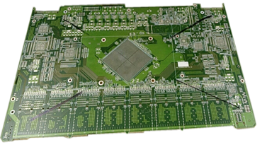
The above picture shows a customer's product. The thickness of the substrate is 4 mm. The heat-absorbing soldering iron has a high temperature and long time, which often scratches the pad. After the customer uses the VT-610ML to remove the tin, there is no problem such as scratching the pad.
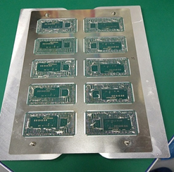
In the figure above, there is a device in the middle of the customer product pad. In the process of removing the tin by the soldering iron, the intermediate device is often scrapped, and the efficiency is low. The customer uses the VT-610PCBA substrate tin-removing machine. Since the tin-removing machine is non-contact type tin-removing, it does not touch the intermediate parts of the pad. After the board is joined together, the efficiency is also very high.
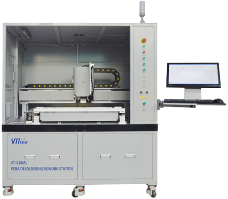
【Fully automatic PCBA substrate tin removal machineVT-610】

10、PTH through-hole device high quality rework
PTH through-hole component SnPb solder joint cracking induced December 2014 Indonesian aircraft crash report

On the morning of December 28, 2014, the Airbus A320-216 AirAsia QZ8501 passenger plane crashed in the Java Sea on the way from Surabaya, the second largest city in Indonesia, and 156 passengers and 6 crew members were killed.
On June 16, 2015, the Indonesian National Transportation Safety Board will ship the aircraft control unit module (shown in Figure 1), which was found from the crash point, to British European Airlines (BEA) for professional testing. It is indeed found in the A and B channels. There is solder joint cracking (shown in Figure 2), and the cracked solder joints cause the electrical connection to be interrupted, causing the RTLU to fail. This is also related to the maintenance record of the aircraft indicating that there were up to 23 failures in the RTLU in 2014 before the crash, especially in the past three months.
This is due to a crash caused by poor solder joint welding. Professor Zhang Xinping from South China University of Technology (Guangdong Province Electronic Packaging Materials and Reliability Engineering Technology Research Center) said: "The reliability of solder joints is also related to electronic design, process technology, solder and The electronic component materials and service conditions are closely related, and the failure mechanism of solder joints mainly includes fatigue, creep, corrosion, cracking and brittle fracture, etc. Due to the characteristics of the solder joints in the circuit board of the aircraft control unit module, Power failure during flight and non-flight, strong vibration or impact during take-off and landing, and alternating ambient temperature and high ambient temperature, etc., solder joints are prone to fatigue problems, resulting in cracking and breaking of solder joints, broken soldering The point will cause the electrical connection of the electrical and functional modules to be broken, which will cause the function failure of the system." Therefore, the welding of the solder joints is reliable, which is related to various requirements such as the requirements of the rework station, and the temperature of the rework station. Control, rework device materials and other requirements.

The factory's traditional through-hole device repair is manually repaired by hand dipping small tin furnace. What are the problems with this type of maintenance?
1、Soldering time is too long, causing the pad to fall off
2、Long welding time, copper melting
3、Insufficient welding time, resulting in insufficient depth of tin
4、Insufficient welding time leads to cold welding
5、Deformation of the substrate causes the inner layer to break
6、Thermal shock causes copper breakage
IBM About PTH Rework Specification File
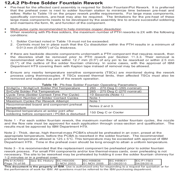

After a customer repaired the through-hole components of a large motherboard such as a server in the traditional way, it was found to be bad when performing functional tests. After the slicing test, the FA engineer showed that the hole wall line had broken and dissolved copper, and there were serious quality problems. The analysis results show that PCBA is subjected to thermal shock and immersion time is too long.
After being repaired by the VT-160PTH rework station, the functional test and the reliability verification test are all qualified, and the problem is successfully solved.
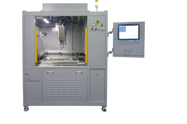
【Fully automatic PTH rework stationVT-160】

Application customer
Taiwan Zhibang, Huawei, Foxconn, Elite Computer, Compal Computer, Jinbao Electronics, Shennan Circuit
11、Pop chip ball
12、Oversized metal BGA ball
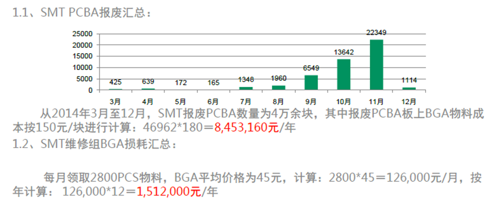
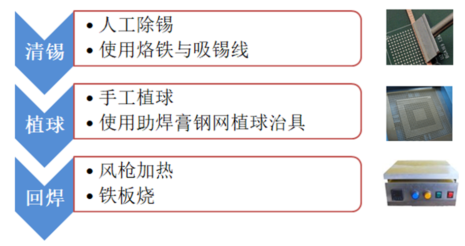
The above picture shows the scrapped cost of BGA materials calculated by a well-known mobile phone manufacturer in China within one year. This shows that BGA ball planting, resource recycling can save a lot of cost for the factory.
Problems with traditional ball placement methods
1、Soldering iron in addition to tin scrap rate is high
2、Soldering iron has low efficiency in removing tin
3、Hole pads such as POP cannot be removed
4、Ball diameter below 0.3mm can not be artificially implanted
5、The traditional soldering method has poor temperature reliability and has hidden quality problems.
6、High staff dependency and high labor costs
VTTECH efficient ball placement solution
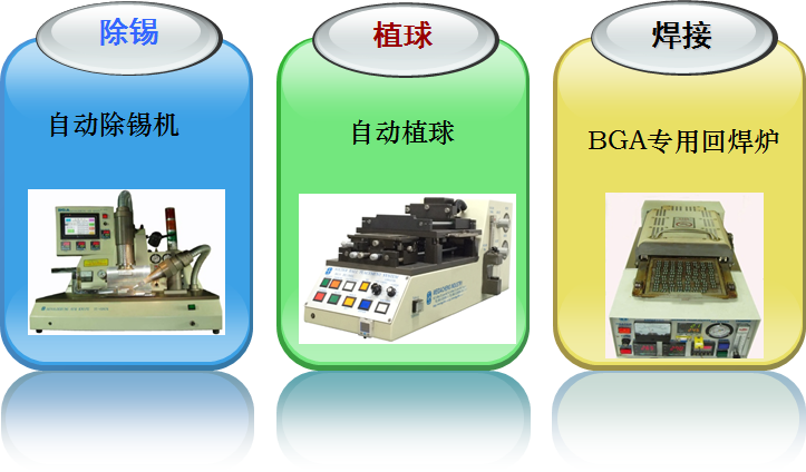
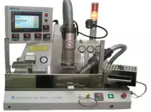
Daily production capacity(8小时):2000-4000颗

Automatic non-contact tin removal can be quickly applied to BGA chips (including POP/QFN, etc.) that need to be ball-planted. The automatic tin-removing knife removes tin quickly and efficiently, and does not need to absorb tin. Line, no damage to the BGA chip PAD.
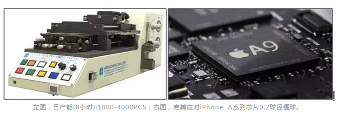
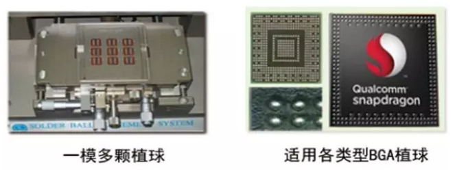
The BGA chip is placed on the automatic ball planting ball lifting platform to start the ball planting machine, and the machine automatically brushes the ball to the BGA chip PAD. The implantable ball diameter is 0.20mm -0.75mm; can carry out multiple ball planting; rapid die change function.

TU-380 reflow oven is suitable for all kinds of BGA reflow ball planting;
Fast and efficient, with an average of 2.5 minutes/Cycle;
Non-contact heating, BGA is heated to avoid thermal shock evenly;
Nitrogen welding, tin balls are as bright as new
One-button operation automatically starts and completes welding;
Automatically generate BGA reflow parameters.
13、PCBA substrate SMD device repair
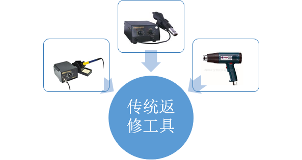
The PCB substrate of the server and Netcom products is large and thick. When using a traditional soldering iron or air gun to repair the on-board device, the following problems occur:
1、The substrate absorbs heat, and the soldering iron gun needs to set a higher temperature, which is not safe.
2、Air gun heating welding time is uncontrollable
3、Long repair time and low efficiency
![]()
The SMD rework plan recommended by VTTECH is: zone preheating + upper programmable main heating.
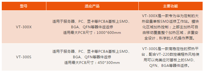
Therefore, VTTE introduced the VT-300 series SMD rework station to replace the traditional substrate SMD device rework tool. This method not only improves the rework efficiency of the SMD device, but also provides a reliable guarantee for the rework quality of the SMD device....

At this point, the 13 major problems of PCBA rework were solved. The attendees said that the 13 major solutions mentioned in this conference are very useful for them because they are facing similar problems. Then, the participants visited the equipment demonstration together.
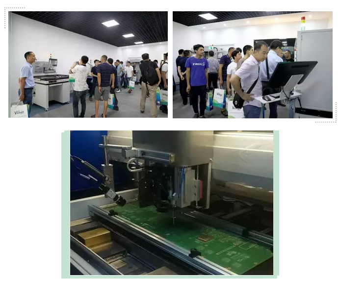
After visiting the equipment, the guests went to the hotel to eat, and the meeting was successfully concluded. Based on solving the PCBA rework industry problem, this conference is the world's first systematic PCBA rework seminar, leading the PCBA rework trend and laying the foundation for the PCBA rework industry.
 中文网站
中文网站 English